


 English
  русский
  Español
  عربى
عربى  日本語
日本語 

What Is Bearing Steel and How Do You Choose the Right Bearing
 2026.09.21
 Industry News
Content
- 1 Bearing Steel: The Metallurgical Foundation Behind Every Rolling Contact
- 2 Six Performance Requirements That Define Bearing Steel
- 3 Chemical Composition: How Each Element Earns Its Place
- 4 The Bearing Steel Grade Families
- 5 The Four Classes of Steel and Where Bearing Steel Fits
- 6 The Eight Common Rolling Bearing Types and Their Material Demands
- 7 Three Bearing Groupings by Rolling Element Geometry
- 8 Bearing Steel Versus Stainless Steel: A Parameter-Level Comparison
- 9 Temperature Behaviour: Where Each Material Stops Performing
- 10 Bearing Life: The L10 Calculation and What Actually Drives It
- 11 Material Selection Matrix by Operating Condition
- 12 Manufacturing Route: From Melt to Finished Raceway
- 13 Quality Control Parameters and Acceptance Limits
- 14 Tolerance Classes and Size Ranges
- 15 Lubrication, Fit, and Installation: Where Bearing Life Is Actually Lost
- 16 Failure Modes and Their Material Signatures
- 17 Product Range and Customization Capabilities
- 18 Applications Served by Precision Bearing Steel Components
- 19 Frequently Raised Technical Questions
- 20 Specifying Bearing Steel Correctly
Bearing Steel: The Metallurgical Foundation Behind Every Rolling Contact
Every rotating assembly in modern machinery depends on a handful of highly engineered contact points. A pump running at 3,600 rpm, a gearbox carrying 40 kN of radial load, a conveyor pulley turning twenty-four hours a day — all of them rely on the same physical principle: hardened steel surfaces rolling against each other without losing their geometry. The material that makes this possible is bearing steel, and its specification is far more demanding than most machinery components ever encounter.
Bearing steel is not a single grade. It is a family of steels engineered around one specific failure mode — rolling contact fatigue. Where a shaft might fail from bending, or a bracket from tension, a bearing raceway fails from the accumulation of millions of repeated subsurface stress cycles. That distinction drives every metallurgical decision: carbon content, chromium addition, inclusion control, heat treatment cycle, and surface finish. A change of 0.05% in carbon, or a doubling of oxygen content, can shift a bearing's service life by an order of magnitude.
This reference covers the chemistry, the grade families, the relationship between bearing steel and stainless steel, the eight common rolling bearing types, the four broad classes of steel, the L10 life calculation, and the selection logic that connects a load case to a material specification.
Six Performance Requirements That Define Bearing Steel
Rolling contact does not stress a material the way a tensile test does. The load is applied and removed millions of times per hour, concentrated over a contact patch often smaller than a grain of rice. Six properties determine whether a raceway survives that environment.
Hardness
Raceways and rolling elements typically operate between 58 and 64 HRC. Below 58 HRC, plastic deformation and raceway denting appear. Above 64 HRC, fracture toughness drops and the material becomes sensitive to impact.
Rolling Contact Fatigue Resistance
The ability to resist subsurface crack initiation under cyclic Hertzian stress. This is governed primarily by steel cleanliness and the size distribution of non-metallic inclusions.
Wear Resistance
Resistance to material loss at the contact surface, driven by carbide volume fraction and matrix hardness. Relevant in contaminated or marginally lubricated environments.
Dimensional Stability
A bearing that grows 2 µm in diameter over 5,000 hours loses preload control. Retained austenite content and tempering temperature determine how much dimensional drift occurs at operating temperature.
Elastic Limit
The maximum stress a material can sustain without permanent deformation. Bearing steel is engineered to push this limit as high as possible while retaining a workable hardening response.
Cleanliness
Oxygen content and inclusion morphology. A single oxide inclusion of 20 µm located in the maximum shear stress zone can become the origin point of a spall that ends the bearing's life.
Chemical Composition: How Each Element Earns Its Place
The standard high-carbon chromium bearing steel — designated GCr15 in Chinese standards, AISI 52100 in the United States, SUJ2 in Japan, and 100Cr6 in Germany — has a composition that has changed remarkably little in eighty years. The reason is that each element performs a specific function, and deviations in either direction carry a penalty.
| Element | Typical Range | Function in the Material |
| Carbon (C) | 0.95% – 1.05% | Forms martensite on quenching; supplies carbon for chromium carbide precipitation. Too low and hardness falls short; too high and coarse carbides embrittle the matrix. |
| Chromium (Cr) | 1.30% – 1.65% | Increases hardenability, forms fine carbides that resist wear, and provides modest corrosion resistance. Also raises the tempering resistance temperature. |
| Manganese (Mn) | 0.20% – 0.40% | Improves hardenability and counteracts the negative effect of sulfur. Excessive manganese promotes banding during solidification. |
| Silicon (Si) | 0.15% – 0.35% | Deoxidizer during steelmaking; strengthens the ferrite matrix. Elevated silicon improves tempering resistance but reduces machinability. |
| Phosphorus (P) | ≤ 0.025% | Deliberately limited. Phosphorus segregates at grain boundaries and reduces toughness. Every 0.01% increase measurably shortens fatigue life. |
| Sulfur (S) | ≤ 0.020% | Limited for fatigue applications. Sulfide inclusions act as stress concentrators, though controlled sulfide morphology can improve machinability in non-critical grades. |
| Oxygen (O) | ≤ 12 ppm (vacuum degassed) | The single most influential cleanliness indicator. Oxide inclusions are the dominant crack initiation sites in rolling contact fatigue. |
| Molybdenum (Mo) | 0% – 0.10% (optional) | Added to certain grades to improve hardenability in large section sizes and to resist temper softening. |
The Bearing Steel Grade Families
Not every application can be served by a single grade. Five families cover the practical range of operating conditions encountered in industrial machinery.
High-Carbon Chromium
GCr15, AISI 52100, SUJ2, 100Cr6. The workhorse grade. Through-hardened to 60–64 HRC. Used for deep groove ball bearings, cylindrical roller bearings, and the majority of general industrial bearings. Operating temperature ceiling around 250°C with dimensional stabilization treatment.
Carburizing (Case Hardening)
Grades such as G20CrMo and G20CrNiMo, with base carbon around 0.15%–0.20%. Surface carburized to 58–62 HRC while the core remains at 30–42 HRC. The hardness gradient absorbs shock loading, which makes these grades standard for tapered roller bearings, railway axleboxes, and mining equipment.
Medium-Carbon
Used where moderate hardness and good machinability matter more than maximum fatigue rating. Induction-hardened raceways in low-speed, high-torque applications. Cost per unit is lower, fatigue rating is correspondingly lower.
Stainless Bearing Steel
Martensitic grades such as 440C, and nitrogen-alloyed martensitic variants. Hardness 55–62 HRC with meaningful corrosion resistance. Specified for food processing, chemical handling, marine decks, and medical equipment.
High-Temperature Grades
M50 tool steel and similar secondary-hardening alloys. These retain hardness at 300°C–500°C where conventional bearing steel has already softened below usable levels. Standard in aircraft engine mainshaft bearings and high-temperature furnace applications.
The Four Classes of Steel and Where Bearing Steel Fits
Steel classification in the AISI system divides the entire field into four families. Understanding where bearing steel sits clarifies why it cannot simply be substituted with a cheaper alternative.
Carbon Steel
Iron plus carbon, with no deliberate alloying additions. Low cost, good machinability, low hardenability. Not used for bearing raceways under any significant load.
Alloy Steel
Carbon steel with chromium, nickel, molybdenum, or manganese added for hardenability and mechanical properties. Bearing steel sits here, in the high-carbon chromium subgroup.
Stainless Steel
Chromium content above roughly 10.5%, forming a passive oxide layer. Martensitic stainless grades can be hardened and used in bearing applications; austenitic grades cannot.
Tool Steel
Engineered for cutting, forming, and high-temperature wear resistance. M50 and similar grades cross over into bearing service where temperature exceeds the limit of conventional bearing steel.
The Eight Common Rolling Bearing Types and Their Material Demands
The eight types below cover the vast majority of rolling element bearings in industrial service. Each imposes a different combination of load direction, load magnitude, misalignment tolerance, and speed on the bearing steel used to make it.
1. Deep Groove Ball Bearing
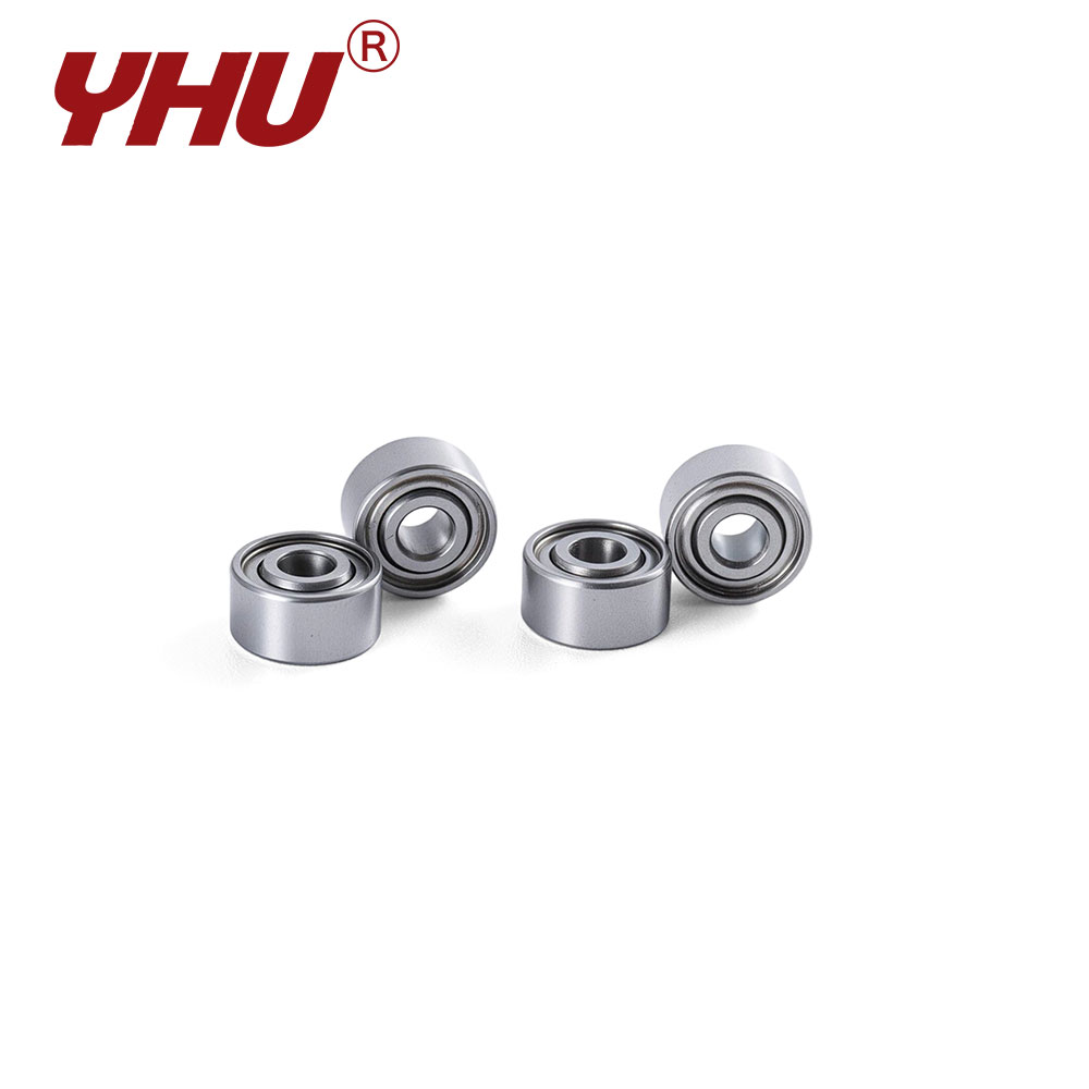
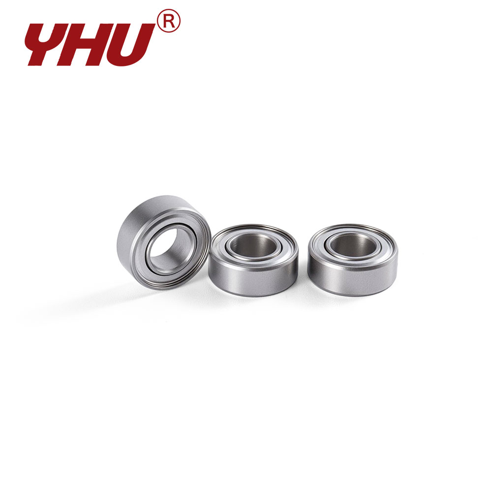
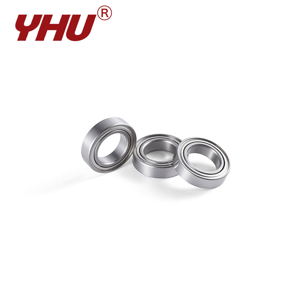
Carries radial and moderate axial load in both directions. The most widely produced type. Demands very high steel cleanliness because the contact ellipse is small and stress concentration is high.
2. Angular Contact Ball Bearing
Designed with a contact angle that supports combined radial and one-directional axial load. Commonly mounted in pairs or sets. Requires tight control of raceway curvature and surface finish.
3. Self-Aligning Ball Bearing
Spherical outer raceway accommodates shaft misalignment. Used in applications where frame deflection cannot be eliminated. Tolerates angular error but carries lower axial load.
4. Cylindrical Roller Bearing
Line contact rather than point contact gives high radial capacity. Available in designs that allow axial float. Roller and raceway alignment is critical; edge loading causes premature failure.
5. Tapered Roller Bearing
Handles combined radial and axial load through a tapered geometry. Frequently made from carburized bearing steel so the core absorbs impact while the surface resists wear.
6. Spherical Roller Bearing
Double-row design with a spherical outer raceway. High radial capacity combined with misalignment tolerance. Common in heavy machinery, crushers, and paper mills.
7. Needle Roller Bearing
Long, thin rollers allow a very small radial cross-section. Used where installation space is limited. The thin section makes raceway hardness and case depth especially important.
8. Thrust Ball Bearing
Carries axial load only. Single-direction and double-direction configurations exist. Not suitable for radial load, and requires adequate minimum axial load to prevent sliding.
Three Bearing Groupings by Rolling Element Geometry
When bearings are grouped by the shape of the rolling element rather than by load direction, three categories emerge. Each produces a distinctly different contact stress pattern, and each places different demands on bearing steel.
| Grouping | Contact Geometry | Load Character | Typical Material Consideration |
| Ball Bearings | Point contact | Lower load capacity, higher speed capability | Highest cleanliness requirement; small contact area amplifies the effect of any inclusion |
| Roller Bearings | Line contact | Higher load capacity, lower speed ceiling | Case depth control critical; edge stress concentration must be managed by profile design |
| Needle Bearings | Line contact, slender roller | High radial capacity in minimal radial space | Thin sections require uniform hardness through the wall thickness |
Bearing Steel Versus Stainless Steel: A Parameter-Level Comparison
The question of whether bearing steel is stronger than stainless steel has a qualified answer. Conventional high-carbon chromium bearing steel achieves higher hardness and higher fatigue rating than any stainless grade used in bearing service. Stainless steel wins on corrosion resistance, and in some cases on high-temperature hardness retention. The two are not interchangeable without re-evaluating the operating environment.
| Parameter | Bearing Steel (GCr15 / 52100) | Martensitic Stainless (440C) | Austenitic Stainless (304 / 316) |
| Hardness (HRC) | 60 – 64 | 58 – 62 | Not hardenable (≤ 20 HRC equivalent) |
| Corrosion Resistance | Low | Moderate to good | Excellent |
| Radial Load Capacity | High | Medium-high | Low |
| Maximum Continuous Service Temperature | ≈ 250°C (with stabilization) | ≈ 300°C | ≈ 300°C (but soft) |
| Magnetic Response | Ferromagnetic | Ferromagnetic | Effectively non-magnetic (316) |
| Rolling Contact Fatigue Rating | Reference baseline | Approximately 70% – 85% of baseline | Not applicable to rolling contact |
| Typical Application | General industrial, automotive, machine tools | Food equipment, marine, chemical, medical | Housings, shields, non-load-bearing components |
Hardness Comparison Across Bearing Materials
The chart below plots achievable surface hardness across the material options most frequently specified for rolling bearings. Carburized steel is shown twice because its defining feature is the difference between surface and core.
Temperature Behaviour: Where Each Material Stops Performing
Hardness retention at elevated temperature separates bearing steel grades more sharply than any room-temperature comparison. A material that reads 62 HRC on the inspection bench may be at 50 HRC inside a hot housing.
Standard high-carbon chromium bearing steel begins losing hardness above roughly 180°C, and the decline accelerates sharply past 250°C. Martensitic stainless holds slightly better through the 200°C–300°C band. Tool steel grades based on secondary hardening maintain usable hardness well beyond 400°C, which is why they appear in applications where the surrounding structure is itself glowing.
Bearing Life: The L10 Calculation and What Actually Drives It
Bearing life is expressed statistically. The L10 rating life is the number of revolutions, or the number of operating hours, that 90% of an identical group of bearings will complete before the first sign of fatigue appears. It is not a prediction for one individual bearing — it is a property of the population.
L10 = (C / P)p × 106 revolutions
L10h = (106 / (60 × n)) × (C / P)p
C = basic dynamic load rating · P = equivalent dynamic load · p = 3 for ball bearings, 10/3 for roller bearings · n = rotational speed in rpm
Worked Example
A deep groove ball bearing with a basic dynamic load rating C of 52 kN carries an equivalent dynamic load P of 5 kN at 1,500 rpm. The life exponent for a ball bearing is 3.
1
Load ratio: C / P = 52 / 5 = 10.4
2
Raise to the life exponent: 10.4³ = 1,124.9
3
L10 = 1,124.9 × 10⁶ revolutions = 1.125 × 10⁹ revolutions
4
L10h = 1.125 × 10⁹ / (60 × 1,500) = 12,499 hours
At eight operating hours per day, that corresponds to roughly 4.3 years of continuous service. Doubling the load to 10 kN would cut the life by a factor of eight — down to approximately 1,562 hours. The cubic relationship means that load estimation errors have a disproportionate effect on the calculated result, and it explains why bearing selection is rarely based on nominal load alone.
Load Ratio Versus Relative Life
The curve below shows how relative life collapses as the load ratio P/C increases. The vertical axis is logarithmic; each major gridline represents a tenfold change.
Life Modification Factors
The basic L10 calculation assumes ideal conditions. Real installations deviate, and the standard provides modification factors that adjust the rating.
| Factor | Symbol | Influenced By | Practical Effect |
| Reliability adjustment | a1 | Required survival probability above 90% | At 99% reliability, a1 = 0.21; at 95%, a1 = 0.62 |
| Material adjustment | a2 | Steel cleanliness, heat treatment quality, oxygen content | Premium vacuum-degassed bearing steel can justify a2 above 1.0; poorly cleaned steel falls below 1.0 |
| Operating condition adjustment | a3 | Lubrication film thickness, temperature, contamination level | Contaminated lubricant can reduce a3 to 0.3 or lower; an adequate elastohydrodynamic film pushes it above 1.0 |
| Combined modification | aISO | Integrated assessment of lubrication and contamination | Replaces separate a2 and a3 in current international practice |
Material Selection Matrix by Operating Condition
The correct bearing material follows from the dominant failure mode in a given application. Where fatigue governs, cleanliness and hardness matter most. Where corrosion governs, chromium content governs. Where temperature governs, tempering resistance governs.
| Operating Condition | Dominant Failure Mode | Recommended Material | Key Parameter to Specify |
| General industrial, normal temperature | Rolling contact fatigue | GCr15 through-hardened | Oxygen content ≤ 12 ppm; hardness 60–64 HRC |
| Heavy shock loading | Core fracture, raceway spalling | Carburizing grade | Case depth 1.5–3.0 mm; core hardness 30–42 HRC |
| Moisture or washdown exposure | Corrosion pitting, then fatigue | Martensitic stainless 440C | Hardness 58–62 HRC; passivation treatment |
| Continuous temperature above 250°C | Hardness loss, dimensional growth | M50 tool steel | Secondary hardening response; retained austenite below 3% |
| Contaminated environment, abrasive particles | Wear, then fatigue initiation | High-carbon chromium with increased carbide volume | Surface hardness at upper end of range; sealed design preferred |
| High speed, light load | Heat generation, lubricant breakdown | Bearing steel races with ceramic rolling elements | Element density approximately 40% lower than steel; reduced centrifugal load |
Manufacturing Route: From Melt to Finished Raceway
The properties specified on a material certificate only survive if the manufacturing sequence preserves them. Each step below contributes to the final fatigue rating.
Primary melting and vacuum degassing
Ladle refining and vacuum treatment reduce oxygen and hydrogen. This step determines the inclusion population and therefore the upper bound of fatigue life.
Continuous casting or ingot casting
Casting practice controls macrosegregation and center porosity. Electromagnetic stirring produces a more uniform carbon distribution.
Hot rolling and forging
Breaks down the cast structure and closes internal porosity. Forging ratio and temperature control determine carbide banding severity.
Spheroidize annealing
Produces a soft, machinable structure with carbides in spheroidal form. Hardness typically drops to 180–210 HB for subsequent turning.
Turning and forming
Raceway geometry is established. Stock allowance is calculated to leave enough material for the hardening distortion that follows.
Quenching and tempering
The critical step. Austenitizing temperature, quench medium, and tempering temperature determine hardness, retained austenite, and dimensional stability.
Grinding and honing
Establishes raceway curvature, surface finish, and dimensional tolerance. Surface roughness below Ra 0.05 µm improves lubricant film formation.
Assembly and inspection
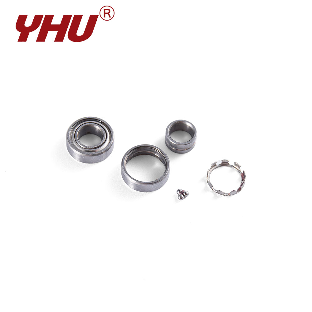
Clearance setting, riveting or cage assembly, noise testing, and final dimensional verification before packaging.
Quality Control Parameters and Acceptance Limits
Incoming material and outgoing product are verified against a defined set of measurements. The limits below reflect typical practice for precision bearing production.
| Inspection Item | Method | Typical Acceptance Limit |
| Oxygen content | Inert gas fusion | ≤ 12 ppm for standard grades; ≤ 8 ppm for premium |
| Non-metallic inclusion rating | Microscopic examination per ISO 4967 | Thin series ≤ 1.5; heavy series ≤ 1.0 |
| Surface hardness | Rockwell C | 60 – 64 HRC (through-hardened); 58 – 62 HRC (carburized surface) |
| Case depth | Microhardness traverse | 1.5 – 3.0 mm to 550 HV for carburized components |
| Retained austenite | X-ray diffraction | ≤ 5% for dimensional stability; ≤ 3% for high-precision applications |
| Decarburization depth | Microhardness or metallographic | Zero total decarburization on raceway surfaces |
| Raceway surface roughness | Profilometer | Ra ≤ 0.08 µm for standard; Ra ≤ 0.04 µm for precision grades |
| Dimensional tolerance | Air gauge or coordinate measurement | Per ISO P6, P5, or P4 class as specified |
| Radial internal clearance | Gauge measurement under defined load | Per C2, CN, C3, C4 groups |
| Vibration and noise | Anderon or BVT tester | Grade Z1, Z2, or Z3 depending on application |
Tolerance Classes and Size Ranges
Bearing steel components are produced across a wide dimensional span, from miniature instrument bearings with a 1 mm bore to large-diameter slewing rings exceeding 2,000 mm. Tolerance class selection follows directly from the precision requirement of the application.
| Tolerance Class | Bore Diameter Range Covered | Typical Application |
| P0 / Class 0 | 1 mm – 200 mm | General purpose machinery, fans, conveyors, household appliances |
| P6 / Class 6 | 1 mm – 500 mm | Electric motors, pumps, agricultural equipment |
| P5 / Class 5 | 3 mm – 500 mm | Machine tool spindles, gearbox shafts, precision reducers |
| P4 / Class 4 | 3 mm – 400 mm | High-speed spindles, measuring instruments, medical equipment |
| P2 / Class 2 | 3 mm – 300 mm | Ultra-precision spindles, semiconductor equipment, aerospace instrumentation |
Lubrication, Fit, and Installation: Where Bearing Life Is Actually Lost
A correctly specified bearing steel grade can still fail in a fraction of its calculated life if the installation is wrong. Field failure analysis repeatedly points to the same causes.
Insufficient Lubricant Film
When the elastohydrodynamic film thickness drops below roughly three times the composite surface roughness, asperity contact occurs and surface-initiated fatigue accelerates. Viscosity selection must be based on operating temperature, not ambient temperature.
Incorrect Interference Fit
An excessively loose fit allows the inner ring to creep on the shaft, generating wear debris and heat. An excessively tight fit induces hoop stress that adds to the service load and reduces fatigue life.
Misalignment
Angular misalignment concentrates load at one edge of the raceway. Even a fraction of a degree shifts the stress distribution enough to reduce life by half in a cylindrical roller bearing.
Contamination During Mounting
Particles introduced during installation become permanent abrasives inside the bearing. Cleanliness during assembly has a measurable effect on subsequent service life.
Overload at Startup
Starting torque in heavily loaded equipment can exceed the steady-state load by a factor of two or more. This is particularly damaging to bearings selected on steady-state load alone.
Electrical Erosion
In motors driven by variable-frequency controllers, shaft currents discharge through the bearing and produce fluting on the raceway. Ceramic-coated or hybrid bearings interrupt the current path.
Failure Modes and Their Material Signatures
Different failure mechanisms leave different marks on the raceway. Reading those marks backwards leads to the material or installation variable that needs correction.
| Failure Mode | Visual Signature | Root Cause Category |
| Rolling contact fatigue | Subsurface-origin spalling with a defined edge | Inclusion content, load history, life exhaustion |
| Surface distress | Shallow, rough, dull raceway with fine pitting | Inadequate lubricant film, low viscosity, high temperature |
| Wear | Material removal across the raceway, dimensional change | Abrasive contamination, insufficient lubrication |
| False brinelling | Regularly spaced indentations matching ball spacing | Vibration during transport or standstill, micro-movement |
| Smearing | Localized surface tearing and material transfer | Sliding under insufficient load, rapid acceleration, poor fit |
| Electrical fluting | Washboard pattern perpendicular to rolling direction | Shaft current discharge |
| Fracture | Ring or ball cracking, often at a single location | Impact overload, incorrect fit, inadequate core toughness |
| Corrosion | Rust staining, etching, or pitting on raceway and balls | Moisture ingress, inadequate preservative, acidic lubricant |
Product Range and Customization Capabilities
Standard catalog bearings cover a large share of industrial demand, but many applications require geometry, clearance, or material adjustments that are not available off the shelf. The list below describes the modification dimensions that are routinely accommodated in production.
Material Substitution
Raceway and rolling element material can be specified as high-carbon chromium bearing steel, carburizing grade, martensitic stainless, or high-temperature tool steel within the same envelope dimensions.
Clearance Groups
Radial internal clearance can be set to C2, CN, C3, C4, or C5 to match the thermal expansion and fit conditions of a specific assembly.
Seal and Shield Configuration
Open, shielded, or sealed variants are produced on the same raceway geometry. Seal material selection includes nitrile rubber, fluoroelastomer, and polytetrafluoroethylene for elevated temperatures.
Cage Design
Steel riveted, brass machined, or polyamide snap cages are available depending on speed rating, temperature, and lubrication regime.
Surface Treatment
Black oxide coating for corrosion protection and lubricant retention, or thin dense chromium plating for wear resistance in marginally lubricated conditions.
Precision Upgrading
Standard production can be sorted or selectively finished to P5, P4, or P2 tolerance classes without changing the design envelope.
Non-Standard Dimensions
Bore, outer diameter, and width combinations outside published catalogs are produced from tooling designed for the specific application.
Lubricant Pre-Filling
Sealed bearings can be filled with a specified grease grade and quantity, matched to the operating temperature range and speed factor of the application.
Applications Served by Precision Bearing Steel Components
Different industries stress bearing steel in different ways. The table below maps the dominant requirement to the sector.
| Industry | Typical Bearing Types | Dominant Material Requirement |
| Electric motors and generators | Deep groove ball, cylindrical roller | Low noise, controlled clearance, dimensional stability |
| Automotive drivetrain | Tapered roller, deep groove ball, needle roller | High fatigue rating, consistent hardness, tight tolerance |
| Machine tool spindles | Angular contact ball, cylindrical roller | P4 or P2 tolerance, low heat generation, high rigidity |
| Agricultural machinery | Spherical roller, tapered roller, insert bearings | Contamination tolerance, sealed design, shock resistance |
| Food and beverage processing | Stainless deep groove ball, stainless insert bearings | Corrosion resistance, washdown compatibility, non-toxic lubricant |
| Mining and aggregate processing | Spherical roller, tapered roller | Case-hardened surfaces, high load rating, robust sealing |
| Marine and offshore | Stainless ball, spherical roller | Salt spray resistance, galvanic compatibility |
| Semiconductor manufacturing | Precision angular contact, hybrid ceramic | Cleanroom compatibility, low outgassing, non-magnetic options |
Frequently Raised Technical Questions
What is bearing steel used for beyond bearings?
High-carbon chromium bearing steel is also used for valve balls, gauge blocks, precision shafts, cam followers, and certain cutting tools where a combination of hardness and dimensional stability is required. Its high cleanliness makes it suitable for any application where subsurface fatigue under cyclic contact is a design concern.
Can a stainless bearing replace a standard bearing directly?
Dimensionally, in most cases, yes. Mechanically, not without review. Stainless grades generally carry a lower dynamic load rating than the equivalent high-carbon chromium bearing, and the rating table should be consulted before substitution. In corrosive environments the trade-off is usually favourable; in high-load applications it may not be.
How is bearing life affected by operating speed?
Speed enters the life calculation linearly in the denominator of the hour-based formula. Doubling the speed halves the L10 life in hours, though the life in revolutions remains unchanged. Speed also affects lubricant film formation and heat generation, which feed back into the modification factors.
What clearance should be specified for a high-temperature application?
Higher operating temperatures cause greater thermal expansion of the inner ring relative to the outer ring, which reduces internal clearance. A larger clearance group — C3 or C4 instead of CN — compensates. The required increase depends on the temperature differential between inner and outer ring, which in turn depends on the heat path through the housing and shaft.
Why does a bearing fail well before its calculated L10 life?
In the majority of cases the cause is not the material. Contamination, insufficient lubricant film, incorrect fit, misalignment, or electrical erosion account for most premature failures. The L10 calculation assumes clean lubricant, adequate film thickness, correct installation, and load applied in the designed direction. Deviation from any of these invalidates the result.
How does oxygen content in bearing steel relate to service life?
Oxygen content is a proxy measurement for oxide inclusion population. Inclusions act as stress concentrators in the subsurface zone where maximum shear stress occurs. Reducing oxygen from 20 ppm to 8 ppm has been demonstrated to extend fatigue life substantially under clean lubrication conditions, though the benefit narrows when contamination dominates the failure process.
Specifying Bearing Steel Correctly
A bearing specification that names only the dimensions leaves the most important variables undefined. The material grade, hardness range, cleanliness level, tolerance class, clearance group, and lubricant fill all influence whether the component reaches its calculated life. When these parameters are stated explicitly, the comparison between quotations becomes meaningful and the risk of unexpected field failure drops.
For applications that fall outside standard catalog coverage — unusual dimensions, elevated temperature, corrosive exposure, or non-standard clearance requirements — the specification should be developed together with the manufacturing process rather than applied as an afterthought. The properties that determine rolling contact performance are established at the melting stage and preserved through every subsequent operation. Once that chain is understood, bearing selection stops being a matter of catalog lookup and becomes a controlled engineering decision.

Message Feedback

Professional Manufacturer of Precision Bearings
- Contact Information
-
-
+86 162 6918 9999 +86 136 1619 2555

-
+86 153 0641 4247

-
jeffrey@yhu1988.com

rose@yhu1988.com -
Yinghong Industrial Park, Zexin Avenue, Xingou Auto Parts Industrial Park, Funing County, Yancheng City, Jiangsu Province, China

-
- QR Code
Copyright ©
Jiangsu Yinghong Transmission Technology Co., Ltd.
All Rights Reserved.
Custom Miniature Ball Bearing Manufacturers

